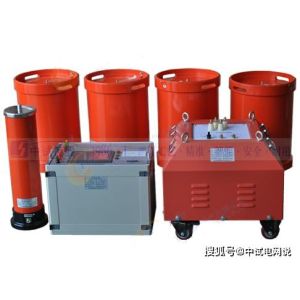
Single-Channel Partial Discharge Tester
Introduction
A single-channel partial discharge tester is a fundamental tool used to capture and analyze electromagnetic signals generated by partial discharges inside power equipment. These signals are captured by sensors and converted into electrical signals, which are then fed into the tester for amplification, processing, and analysis. A single-channel partial discharge tester is typically equipped with one detection channel to monitor partial discharge signals within a single frequency range.
Working Principle
When partial discharge occurs, signals such as electromagnetic waves, acoustic waves, or electrical pulses are generated. The single-channel partial discharge tester operates through the following key components:
Preamplifier: Used to capture and amplify weak discharge signals transmitted from high-voltage equipment.
Filter: Selects signals within a specific frequency range to exclude interference.
Main Amplifier: Further amplifies the signal to a detectable level.
Display Unit: Displays graphical and numerical information of discharge pulses.
Usage Method
Startup Preparation: Set the time base mode to “Ellipse” mode.
Calibration: Correctly connect the calibration pulse generator and enable calibration.
After Calibration: Disconnect the calibration connection line and remove the calibration pulse generator.
Connect to High-Voltage Circuit: Connect to the high-voltage test circuit power supply, turn on the zero-mark switch, and slowly increase the test voltage.
Observe Discharge: Two zero-mark pulses appear on the display ellipse, with a phase difference of 180 degrees. Rotate the “Ellipse Rotation” to a position convenient for observing discharge, then continuously increase the voltage, noting any continuous discharge that appears.
Measure Discharge Voltage: When the discharge amount exceeds the specified low value, the voltage at that time is the partial discharge inception voltage.
Adjust Amplifier: At the set voltage, when discharge pulse signals are observed, adjust the amplifier switch so that the discharge pulse height is between 0.2 and 2 cm. The discharge amount is then the reading on the digital meter multiplied or divided by 10.
Application Scope
Single-channel partial discharge testers are widely used in the maintenance and testing of power systems, especially for partial discharge detection in power equipment such as transformers, cables, switchgear, and generators.
Precautions
Safe Operation: Ensure all operations comply with safety regulations before use to avoid electric shock risks.
Environmental Factors: Consider the influence of ambient temperature, humidity, etc., on test results.
Interference Sources: Minimize the impact of external interference sources, such as electromagnetic interference.
Regular Calibration: Ensure the accuracy and reliability of the test equipment by performing regular calibration.
Technical Specifications
Frequency Range: Typically covers a frequency range from tens of kilohertz to hundreds of megahertz.
Sensitivity: Capable of detecting very small discharge signals.
Linearity: Ensures good linear response across different discharge magnitudes.
Range: Provides multiple ranges for user selection to suit different testing needs.
Conclusion
The single-channel partial discharge tester is an important tool in the power industry for preventing and diagnosing partial discharge issues in electrical equipment. Through early detection of partial discharge phenomena, it can effectively avoid equipment failures and damage, thereby ensuring the stable operation of the power system.
The above is an overview of the single-channel partial discharge tester. If you need more detailed information or suggestions on specific application scenarios, please feel free to let me know.