Working Principle
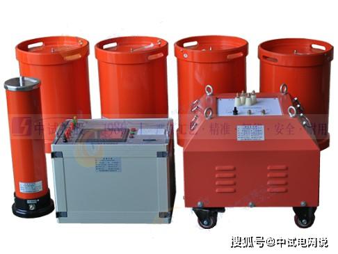
The basic principle of the partial discharge detector is to detect high-frequency pulse currents. When partial discharge occurs under the test voltage, the pulse control signal of the partial discharge detector will be discharged through the system coupling capacitor and sent to the input data unit. Then, through the information input unit, the pulse signal pickup is amplified by a low-noise amplifier to enhance the pulse signal. In the filter amplifier, the desired frequency band is selected, and after amplification by the main amplifier, the required pair of values and zero-mark pulses are achieved. Above the elliptical scanning baseline on the oscilloscope screen, visible discharge pulses will be generated. They will also be sent to the pulse peak value, and its peak value can also be displayed. The internal control system of the time window unit tests the voltage and displays the working time of a pulse peak meter weekly. During this period, the corresponding display area can also be highlighted on the oscilloscope screen to eliminate fixed-phase interference.
Operating Methods
The operating methods of the partial discharge detector mainly include the following steps
Sensor Selection: Select appropriate sensors (such as ultrasonic sensors, TEV sensors, high-frequency current sensors, etc.) based on the different equipment under test (such as transformers, switchgear, GIS, etc.).
Sensor Installation: Use different installation methods for different sensors. For example, some sensors need to be adhered to the equipment surface with adhesive, while others may require handheld scanning.
Host Settings: Set parameters such as test channels, sensor types, measurement modes (single measurement or continuous measurement), units, etc.
Start Testing: Choose manual or automatic settings based on actual conditions, then start the test.
Data Analysis: Analyze discharge counts, waveform characteristics, etc., through horizontal or vertical comparison to determine whether partial discharge phenomena exist in the equipment.
Precautions
Safety First: Ensure compliance with all safety regulations, especially during on-site testing.
Correct Wiring: Ensure that sensors are correctly installed and connected to the host.
Environmental Factors: Consider the impact of environmental factors (such as temperature, humidity, etc.) on test results.
Data Interpretation: Correctly interpret test data, especially for complex waveform analysis.
Regular Maintenance: Regularly maintain and calibrate the detector.
Conclusion
The partial discharge detector is one of the important tools in power system maintenance. It helps technical personnel detect potential problems in equipment in a timely manner and take measures to prevent equipment failures. By reasonably using the partial discharge detector, the safety and reliability of the power system can be effectively improved. If you need more detailed information or encounter specific issues, please feel free to ask.