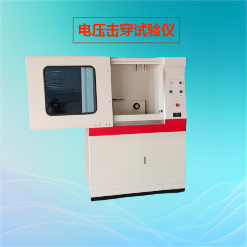
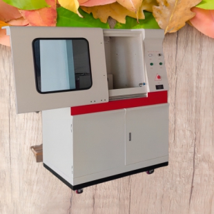
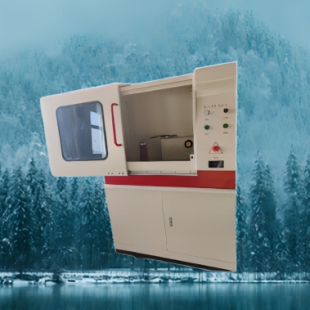
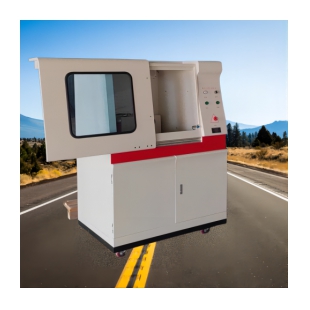
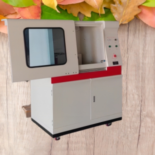
Microcomputer-controlled voltage breakdown tester electrodes and specimens
Metal electrodes should always be kept smooth, clean, and free from defects.
Note 1: When testing thin specimens, the maintenance of electrodes is particularly important. To minimize electrode damage during breakdown, stainless steel electrodes are preferred.
The wires connected to the electrodes should neither cause the electrodes to tilt or move nor change the pressure on the specimen, nor significantly affect the electric field distribution around the specimen.
Note 2: When testing very thin films (e.g., <5μm thick), the product standard for these materials should specify the electrodes to be used, the specific operating procedures, and the specimen preparation method.
5.1 Tests perpendicular to the surface of non-laminated materials and perpendicular to the layers of laminated materials
5.1.1 Plant materials and sheet materials (including paper-based, paper, fabric, and film)
5.1.1.1 Electrodes of unequal diameters
The electrodes consist of two metal cylinders with edges rounded to a radius of (3.0±0.2) mm. One electrode has a diameter of (25±1) mm and a height of about 25 mm, while the other has a diameter of (75±1) mm and a height of about 15 mm. The two electrodes are placed coaxially with an error within 2 mm, as shown in Figure 1a). 1. Insulation specimens undergo breakdown, withstand voltage, or step tests in air at high and low temperatures;
2. Insulation specimens undergo breakdown, withstand voltage, or step tests in oil at high and low temperatures;
3. Insulation specimens undergo breakdown, withstand voltage, or step tests in air;
4. Insulation specimens undergo breakdown, withstand voltage, or step tests in oil;
Test software:
1. Independent control system, modular structure for easy after-sales maintenance, elegant and atmospheric appearance, no noise during the entire experiment, automatic electrode centering and positioning, convenient operation, high safety factor, and high precision.
2. The equipment is operated and controlled via its own touch screen and control panel. If curve analysis is not required, a computer is not necessary.
3. If curve analysis is required, a computer is provided only for data and curve recording, not for equipment control, avoiding the need for testers to alternate between computer and equipment, making it more user-friendly.
4. The equipment has test parameters; under the same test conditions, it is not necessary to set them for each test, and the last test parameter settings are memorized even after power failure.
5. The test interface is simple and clear, with schematic curve explanations; different parameters result in different curve trends, making it easy to understand.
6. The control panel is concise, with clear function labels and simple operation.
7. It can record and display up to 10 test records simultaneously, facilitating comparative analysis of test data. Any unsatisfactory set of data can be discarded at any time.
8. Added U-disk download function, allowing test records in the equipment to be directly downloaded to a U-disk.
9. If equipped with a computer, detailed test reports can be generated, including specific information for each group, comprehensive information for multiple groups, and curves.
10. The equipment test interface uses both a dashboard and digital display simultaneously in real-time, making the test process easier to observe.
Microcomputer-controlled voltage breakdown tester
Instrument composition:
1. Voltage boosting component: consists of a voltage regulator and a step-up transformer;
2. Drive component: controller and motor drive the step-up transformer uniformly;
3. Detection component: measurement circuit composed of integrated circuits;
4. Computer measurement and control system;
5. Box control system
7. Instrument advantages:
1. *Automatic discharge;
2. *AC voltage and DC voltage test error 1%;
3. *Electrode bracket made of high-quality epoxy board;
4. *Software can continuously perform 10 groups of tests for comparison;
5. *Test curves in different colors, can be overlaid for comparison;
6. *Software can set current protection function;
7. *With host control area, the host can be controlled independently without a computer;
8. *Host has voltage and current display functions;
9. *Built-in exhaust device;
10. *Built-in lighting function;
11. *Discharge alarm device;
12. *Bluetooth remote control;
13. *Three-color light alarm device (green light: box door closed properly, yellow light: open door with caution, red light: high voltage present);
14. *Dual operation via touch screen or computer;
15. *Combined programming, with separate settings for voltage rise and withstand time in step voltage rise;
16. *U-disk download function, allowing test records in the equipment to be directly downloaded to a U-disk.
Introduction to two test modes of the paint film power frequency voltage breakdown tester:
The selection of test mode is carried out in the system settings. It should be noted that for AC tests, the silicon stack short-circuit rod needs to be inserted. For DC tests, the silicon stack short-circuit rod must be pulled out to avoid affecting the experimental coefficient, and after DC tests, a discharge operation must be performed to prevent residual charge from posing a danger to experimenters. During discharge, if the discharge rod swings back and forth, the alarm light flashes, and the buzzer alarms; wait until the buzzer stops and the alarm light no longer flashes before opening the test box door.
Introduction to three test methods:
Continuous voltage rise: Continuous voltage rise is divided into fast rise and slow rise. Fast rise means the specimen voltage rises uniformly from zero at the selected rate until breakdown, with the breakdown voltage being the voltage value at the moment of breakdown. Slow rise means the specimen voltage rises from zero to the initial voltage, then rises at the selected rate until breakdown, with the breakdown voltage being the voltage value at the moment of breakdown.
Step voltage rise: The specimen voltage rises rapidly from zero to the initial voltage, then maintains the voltage for the gradient hold time, after which it continues to rise at the selected rate to the next gradient voltage value, then stabilizes again, repeating until breakdown. The determination of breakdown voltage is divided into two cases, and the sampling mode can be selected in the specimen settings.
Instantaneous voltage rise: The specimen voltage directly reaches the initial voltage, maintains this voltage for the set time until breakdown, with the breakdown voltage being the voltage value at the moment of breakdown.
5.1.1.2 Electrodes of equal diameters
If an electrode holder is used to accurately center the upper and lower electrodes within an error of 1.0 mm, the lower electrode diameter can be reduced to (25±1) mm, with a diameter difference between the two electrodes not exceeding 0.2 mm. The results obtained may not necessarily be the same as those obtained with unequal diameter electrodes in 5.1.1.1.
5.1.1.3 Testing of thick specimens
When specified, plates and sheets with a thickness exceeding 3 mm should be machined on one side to (3.0±0.2) mm. Then, during testing, the high-voltage electrode is placed on the unmachined surface.
Note: To avoid flashover or due to limitations of existing equipment, the specimen can be machined to a smaller thickness as needed.
5.1.2 Tapes, films, and narrow strips
The two electrodes are two metal rods with a diameter of (6.0±0.1) mm, vertically mounted in an electrode holder so that one electrode is above the other, with the specimen clamped between the two end faces of the rods.
The upper and lower electrodes should be coaxial with an error within 0.1 mm. The end faces of the two electrodes should be perpendicular to their axes, and the edges of the end faces should be rounded to a radius of (1.0±0.2) mm. The upper electrode pressure is (50±2) g and should be able to move freely in the vertical direction within the electrode holder.
Figure 2 shows a suitable device. If the specimen needs to be tested under tension, it should be clamped in the holder so that the specimen is placed in the specified position as shown in Figure 2. To achieve the required tension, a convenient method is to wrap one end of the specimen around a rotatable rod.
To prevent flashover at the edges of narrow strips, a film or other thin insulating material strip can be placed over the edges and clamped with the specimen. Additionally, anti-arcing seals can be used around the electrodes, leaving a ring gap of (1-2) mm between the electrode and the sealing ring. The gap between the lower electrode and the specimen (before the upper electrode contacts the specimen) should be less than 0.1 mm.
Note: For testing films, see IEC 60674-2, 1998.
5.1.3 Flexible hoses and flexible sleeves
Test according to GB/T7113.2-2005.
5.1.4 Rigid tubes (with inner diameter of 100 mm and below)
The outer electrode is a metal foil strip (25±1) mm wide, and the inner electrode is a conductor that fits tightly against the inner wall, such as a rod, tube, metal foil, or filled with metal balls of diameter (0.75-2.0) mm, ensuring good contact with the inner surface of the tube. In any case, each end of the inner electrode should extend at least 25 mm beyond the outer electrode.
Note: When there are no harmful effects, silicone oil, silicone grease, or petroleum jelly can be used to attach the foil to the inner and outer surfaces of the specimen.
5.1.5 Rigid tubes (with inner diameter greater than 100 mm)
The outer electrode is a metal foil strip (75±1) mm wide, and the inner electrode is a circular metal foil with a diameter of (25±1) mm. The metal foil should be sufficiently flexible to conform to the curvature of the cylinder. The device is shown in Figure 3.
Cast and molded materials: Cast materials are sampled and tested according to IEC 60455-2: 1998.
Molded materials should use a pair of spherical electrodes, each with a diameter of (20.0±0.1) mm, arranged so that their common axis is perpendicular to the specimen plane (see Figure 4).
5.1.6.2.1 Thermosetting materials
Specimens with a thickness of (1.0±0.1) mm should be used. These specimens can be compression molded according to ISO 295: 1991 or injection molded according to ISO 10724: 1994, with surface dimensions sufficient to prevent flashover (see 5.3.2).
Note: If specimens with a thickness of (1.0±0.1) mm cannot be used, specimens with a thickness of (2.0±0.2) mm can be used.
5.1.6.2.2 Thermoplastic materials
Injection molded specimens according to ISO 294-1: 1996 and ISO 294-3: 1996 of the same type should be used, with dimensions of 60 mm × 60 mm × 1 mm. If these dimensions are insufficient to prevent flashover (see 5.3.2) or if the relevant material standard requires compression molded specimens, then flat specimens compression molded according to ISO 293: 1986 should be used, with a diameter of at least 100 mm and a thickness of (1.0±0.1) mm.
The conditions for injection molding or compression molding are specified in the relevant material standards. If no applicable material standard exists, these conditions must be agreed upon between the supplier and the buyer. For rigid molded parts that cannot be placed between flat electrodes, opposed spherical electrodes of equal diameter should be used. Typically, electrodes with a diameter of 12.5 mm or 20 mm are used for such tests. Varnishes are tested according to GB/T 1981.2-2003. Filling compounds: The electrodes are two metal spheres, each with a diameter of (12.5-13) mm, placed horizontally coaxially, separated by (1.0±0.1) mm unless otherwise specified, and both embedded in the filling compound. Care should be taken to avoid voids, especially between the two electrodes. Since results obtained with different electrode distances cannot be directly compared, the gap distance must be noted in the test report of the material specification. Tests parallel to the surface of non-laminated materials and parallel to the layers of laminated materials: If it is not necessary to distinguish between damage caused by specimen breakdown and damage caused by surface penetration, the electrodes in 5.2.1 or 5.2.2 can be used, but the electrodes in 5.2.1 should be preferred. When surface damage must be prevented, the electrodes in 5.2.3 should be used. Parallel plate electrodes: For testing plates and sheets, the specimen thickness is the thickness of the material being tested, the specimen surface is rectangular, with a length of (100±2) mm and a width of (25.0±0.2) mm. The two side surfaces of the specimen should be cut into two parallel planes perpendicular to the material surface. The specimen is clamped between metal parallel plates, with the two metal plates 25 mm apart and a thickness of not less than 10 mm, and the voltage is applied to the metal plates. For thin materials, two or three specimens can be appropriately placed (i.e., their surfaces form a suitable angle) to support the upper electrode. The electrodes should be large enough to cover the specimen edges, extending at least 15 mm beyond each side of the specimen. Care should be taken to ensure good contact between the entire area of the upper and lower surfaces of the specimen and the electrodes. The edges of the electrodes should be appropriately rounded (radius of (3-5) mm) to avoid flashover between the edges (see Figure 6). Note: If the existing equipment cannot cause breakdown of the specimen, the specimen width can be reduced to (5.0±0.2) mm or (10.0±0.2) mm. This reduction in specimen width must be specifically noted in the report. This electrode is only applicable for testing rigid materials with a thickness of at least 1.5 mm. Testing rigid tubes: When testing rigid tubes, the specimen is a complete ring or a segment of a ring with an arc length of 100 mm, with an axial length of (25±0.2) mm. The two ends of the specimen should be machined into two parallel planes perpendicular to the tube axis. Place the specimen between two parallel plate electrodes and test according to the method for plates and sheets described in 5.2.1.1. If necessary, (2-3) specimens can be used to support the upper electrode. The electrodes should be large enough to cover the specimen and extend at least 15 mm beyond each side of the specimen. Care should be taken to ensure good contact between the entire area of the upper and lower surfaces of the specimen and the electrodes.