Three-Phase Relay Protection Test Set - Yangzhou DARUI
DARUI Electric recommends for you
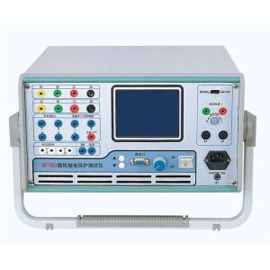
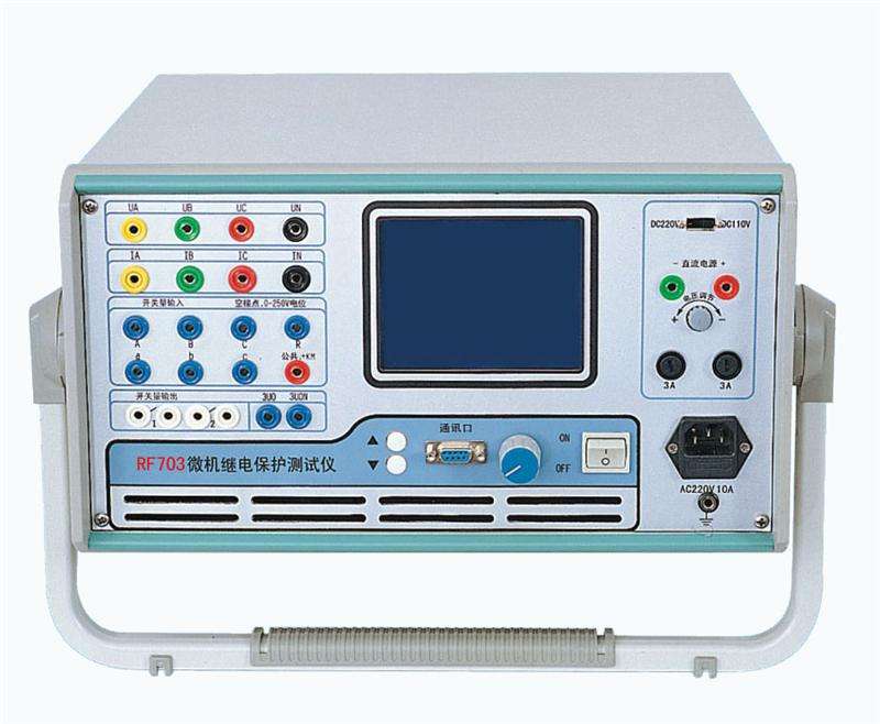
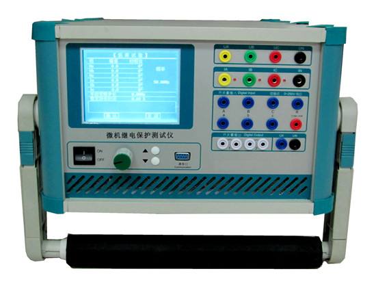
Three-Phase Microcomputer Relay Protection Test Set Product Introduction:
Three-Phase Relay Protection Test Set is a new intelligent test instrument developed in the past decade. The previous relay protection test tools were mainly composed of voltage regulators and phase shifters, which were bulky and had low accuracy, and could no longer meet the calibration work of modern relay protection testing. With the continuous development of science and technology, relay protection test sets have been widely used in various fields such as line protection, main transformer differential protection, and excitation control.
The three-phase microcomputer-based relay protection test device is an important test tool to ensure the safe and reliable operation of the power system. With the rapid development of computer technology, microelectronics technology, and power electronics technology, it is an inevitable trend of technological progress to continuously introduce new high-performance relay protection test devices using new technological achievements. The three-phase relay protection test set, based on the "Technical Conditions for Microcomputer Relay Protection Test Devices" issued by the former Ministry of Electric Power, widely listens to the opinions of Shanghai Lvben Electric Co., Ltd., carefully summarizes the development of previous generations of products, and is developed using modern new digital technology, high-precision electronic devices, microcomputer systems, and new circuits and structures. It can independently complete device testing in professional fields such as microcomputer protection, relay protection, excitation, metering, and fault recording, and is widely used in scientific research and electrical test sites in industries such as electric power, petrochemical, metallurgy, railway, aviation, and military.
The microcomputer relay protection test instrument is divided into two circuits: the main circuit and the auxiliary circuit. The main circuit is adjusted by a large knob, and the auxiliary circuit is adjusted by a small knob. The main circuit controls the various output quantities through the "output selection" button switch on the panel, and each time a different output is switched, the digital voltage/current meter on the instrument can automatically monitor its output value. The auxiliary circuit directly adjusts the output through the output switch control, and the measurement can be done with an external multimeter.
Note: The above information and technical parameters are compiled and released by Yangzhou DARUI Electric Co., Ltd.