Transformer Partial Discharge Detection Device - Yangzhou DARUI
DARUI Electric recommends
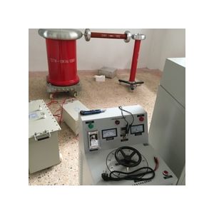
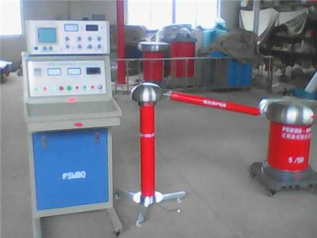
Transformer Partial Discharge Detection Device is small in size and light in weight, making it a truly portable instrument. This instrument is developed based on the IEC (270) standard using the pulse current method, and meets the technical requirements specified in GB-7354-87, GB-1207-97, and GB-1208-97 for partial discharge testing instruments. It features high sensitivity, a large dynamic range in the amplifier system, a wide range of test specimens, and easy operation. It also incorporates advanced anti-interference components and a unique gate display circuit, providing strong anti-interference capability. With four types of high-frequency elliptical scanning, it is suitable for type tests, routine tests, new product development tests of high-voltage products, and quantitative testing of partial discharge in motors, transformers, cables, bushings, capacitors, transformers, arresters, switches, and other high-voltage electrical apparatus. It can be used on-site by manufacturers, research institutions, and power departments.
Partial discharge refers to discharge occurring in a localized part of insulation, which does not constitute a complete breakdown of the entire insulation. It includes three forms of discharge: internal discharge (inside the dielectric), surface discharge (on the dielectric surface), and corona discharge (at electrode tips).
When a certain amount of charge is instantaneously injected at both ends of the test object, causing the change in terminal voltage of the test object to be the same as that caused by partial discharge itself, this injected quantity is the apparent charge of the partial discharge.
3. Apparent Discharge Calibrator
The apparent discharge calibrator is a standard charge generator. Before the test, it outputs a fixed charge to both ends of the test object, simulating the response of the partial discharge tester when the test object discharges at this charge. At this time, the scale factor is adjusted to determine the range of the partial discharge detector, so as to measure the apparent discharge of the test object at rated voltage during the test. Since this discharge is indirectly measured by comparison with the standard charge generator, rather than directly measured, it is called "apparent discharge."
The calibration charge generator is an essential instrument for measuring partial discharge, and its performance parameters directly affect the accuracy of test results.
The apparent discharge calibrator consists of a calibration pulse voltage generator and a calibration capacitor connected in series. Its main parameters include: pulse waveform rise time, decay time, internal resistance, pulse peak value, calibration capacitance value, etc.
The rise time of the calibration pulse voltage generator waveform is defined as the time from 0.1U0 to 0.9U0, and the decay time is defined as the time from the peak value to 0.1U0.
4. Detection Impedance
Detection impedance is a device for picking up detection signals. In use, appropriate detection impedance should be selected according to different test purposes and types of test objects to improve the sensitivity, resolution, waveform characteristics, and signal-to-noise ratio of partial discharge measurement.
Detection impedance is divided into numbers 1 to 12 according to the tuning capacitance range. (See Table 1)
5. Time Window (Gate Unit)
The time window is a circuit device designed to prevent interference signals larger than partial discharge from entering the peak detection circuit. In actual tests, especially on-site, some interference is inevitably introduced, so the use of the time window is even more important.
The working principle of the time window is to divide the elliptical scanning time base into two parts: conduction (brightened area) and cutoff (non-brightened area). By changing the position and width of the time window, the discharge pulse is placed in the conduction (brightened area), and the interference pulse is placed in the cutoff (non-brightened area). At this time, the meter reading is the value of the discharge pulse, and interference, regardless of its magnitude, will not affect the discharge pulse value. If both time windows are closed at this time, the meter reading is the peak value of the pulses on the entire ellipse.
Note: The above information and technical parameters are compiled and released by Yangzhou DARUI Electric Co., Ltd.