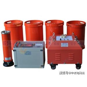
Single-channel partial discharge tester is a professional instrument used to detect partial discharge phenomena in power equipment. This type of tester is typically used to monitor and evaluate the insulation condition of high-voltage equipment such as power transformers, cables, and generators. Below is a detailed article about the single-channel partial discharge tester.
Overview of Single-Channel Partial Discharge Tester
The single-channel partial discharge tester is a professional detection device used to monitor partial discharge phenomena in power equipment. This type of tester is typically applied to power transformers, cables, generators, and other high-voltage equipment to assess their insulation condition and predict potential failures.
Working Principle
The working principle of the single-channel partial discharge tester is based on the detection of signals such as electromagnetic waves, acoustic waves, or electrical pulses generated by partial discharge. When partial discharge occurs in power equipment during operation, a series of pulse signals are generated. These signals are captured through coupling capacitors or other types of sensors and sent to the input unit of the tester. The input unit further transmits these pulse signals to a low-noise preamplifier for amplification, then selects the required frequency band through a filter amplifier, and finally amplifies to the required amplitude by the main amplifier. The amplified signals are displayed as visible discharge pulses on the oscilloscope screen and simultaneously shown on the pulse peak meter.
Usage Methods and Precautions
Usage Methods
Startup Preparation: Adjust the time base mode to "ellipse" mode.
Calibration: Correctly connect the calibration pulse generator and enable calibration.
After Calibration: Disconnect the calibration connection line and remove the calibration pulse generator.
Power Connection: Connect the high-voltage test circuit power supply, turn on the zero mark switch, and slowly increase the test voltage until two zero mark pulses appear on the display ellipse, with a phase difference of 180 degrees. Adjust the "ellipse rotation" to a position convenient for observing the discharge, typically where the zero mark pulses are located at the upper left and lower right of the ellipse.
Discharge Detection: Continuously increase the voltage and pay attention to sustained discharges. When the discharge amount exceeds the specified low value, the voltage at that time is the partial discharge inception voltage.
Adjusting Discharge Pulses: At the set voltage, when discharge pulse signals are observed, adjust the amplifier switch so that the discharge pulse height is between 0.2 and 2 cm. The discharge amount is then the reading on the digital meter multiplied or divided by 10.
Precautions
Before conducting partial discharge tests, ensure all safety measures are in place and comply with relevant safety regulations.
For complex power systems, professional personnel may be required to conduct tests to ensure the accuracy and safety of test results.
Regularly calibrate the tester to ensure its measurement accuracy.
Features and Advantages
High Sensitivity: Can detect very weak discharge pulses.
Wide Applicability: Can be used for partial discharge detection in various high-voltage equipment.
Strong Anti-Interference Capability: Uses advanced anti-interference technology to operate normally in complex electromagnetic environments.
Multifunctional Display: Typically equipped with a large-screen oscilloscope tube or LCD screen, clearly displaying test waveforms and data.
Data Recording and Analysis: Most modern testers have data recording functions, allowing test results to be saved for subsequent analysis.
User-Friendly Interface: Simple and intuitive operation, convenient for field technicians.
Application Scenarios
Power Equipment Maintenance: Used for routine inspection and maintenance of high-voltage equipment such as power transformers, cables, and generators.
Fault Diagnosis: When equipment malfunctions, partial discharge detection is used to diagnose the cause of the fault.
Product Quality Control: Quality control of power equipment during production to ensure the insulation performance of outgoing equipment meets standards.
Research and Development: Used in the development of new power equipment to evaluate the effectiveness of new insulation materials or structures.
Conclusion
The single-channel partial discharge tester plays an important role in the power industry due to its reliable detection capability and flexibility. With technological advancements, future testers will become more intelligent and portable, further improving the efficiency and accuracy of partial discharge detection. By using such testers, power enterprises can not only effectively prevent equipment failures but also significantly enhance the overall reliability and safety of the power system.
The above is an overview of the single-channel partial discharge tester. I hope this article provides you with relevant information and technical details about the single-channel partial discharge tester. If you need more detailed information or specific case analysis, please feel free to let us know.